0. Purpose
The UTS Operator System is the technical architecture that explains how systems change, stabilize, destabilize, repair, invert, couple, and evolve over time.
The operator registry defines the action primitives. This technical module defines the full state-transition environment around them.
In UTS, an operator does not act in isolation. Every operator acts on a shared state vector, manifests through one or more U-layers, is shaped by constraints and gates, produces diagnostic signatures, and may participate in larger recurring regimes.
The core distinction is:
Operators move state. State variables describe what is being moved. U-layers localize where movement occurs. Gates determine admissibility. Diagnostics reveal forced-response behavior. Lenses bias how movement expresses. Regimes name recurring compositions.
This preserves the canon rule that the system does not need new primitives whenever a pattern can be explained as composition, parameterization, diagnostics, or localization. The attached registry explicitly locks this: no new operator primitives, all operators act on a shared state vector, U-layers are localization indices rather than variables, and bandwidth/damping are diagnostics rather than operators.
I. System Architecture Overview
The Operator System has seven major layers:
1. State Layer
   What condition the system is in.

2. Operator Layer
   What changes state.

3. Localization Layer
   Where the change manifests.

4. Interaction Layer
   How systems interface, couple, invite, reflect, amplify, relax, attenuate, or force.

5. Gate / Constraint Layer
   What is admissible, bounded, or nullified.

6. Diagnostic Layer
   How the system behaves under load, stress, forcing, contradiction, and recurrence.

7. Regime Layer
   What recurring composite pattern the system has entered.
These layers should not be collapsed into each other.
A failure to distinguish them creates category errors. For example:
| Mistake | Correction |
|---|---|
| Treating a diagnostic as an operator | Bandwidth does not act; it reveals absorbable forcing. |
| Treating a U-layer as a variable | U4 does not “increase”; classification failure localizes at U4. |
| Treating a regime as a primitive | Crisis Loop is a named composition, not a new operator. |
| Treating a gate as power | Gates determine admissibility, not raw force. |
| Treating Φ as coherence | Φ is a fitness proxy, not O itself. |
II. Core System Equation
A simple technical expression of the Operator System is:
S(t+1) = F[S(t), Ω_op, U, G, Π_gate, D, E]Where:
| Term | Meaning |
|---|---|
S(t) | Current system state |
Ω_op | Applied operator sequence |
U | U-layer localization |
G | Gain stack and lenses |
Π_gate | Gate and constraint conditions |
D | Diagnostic state / forced-response profile |
E | Environment / external forcing |
S(t+1) | Resulting system state after action, delay, stress, or repair |
In plain language:
A system’s next state is determined by its current state, the operators applied, the layer at which they act, the gains and lenses amplifying them, the gates that admit or block them, the diagnostics describing forced response, and the environmental forcing pressing on the system.
This is why UTS can analyze institutions, AI systems, bodies, relationships, economies, symbolic systems, and civilizations with the same operator architecture without reducing them into one domain-specific vocabulary.
III. Canonical State Layer
The state layer answers:
What condition is the system in?
All operators act on subsets of the canonical state vector:
S = { O, H, ε, ι, Au, µᵢ, BΣ, K, R, Φ }The attached registry defines these as coherence, hidden debt, error/noise, inversion index, auditability, agent integrity, boundary integrity, compatibility, restoration capacity, and fitness proxy.
1. State Variables Are Not Operators
A state variable does not act by itself.
For example:
| Variable | What It Is | What It Is Not |
|---|---|---|
| O | Coherence condition | Not an operator |
| H | Hidden debt load | Not a punishment mechanism |
| ε | Observable error/noise | Not the full cause |
| ι | Inversion signal | Not Ξ itself |
| Au | Auditability | Not automatic truth |
| R | Repair capacity | Not repair action itself |
| Φ | Fitness proxy | Not real coherence |
A variable tells us what can change.
An operator tells us how change occurs.
2. State Variables as System Coordinates
The state vector lets UTS track system movement without over-attaching to domain-specific labels.
For example:
| Domain Language | UTS State Translation |
|---|---|
| “The institution looks stable but keeps producing harm.” | O apparent, H↑, ι↑, Au↓ |
| “The metric is improving while the real system worsens.” | Φ↑ while O↓ |
| “The system cannot explain its own decisions.” | Au↓, µᵢ↓ |
| “Repair efforts are too slow for the damage rate.” | R < Load × Gain |
| “Boundaries are blurred between roles.” | BΣ↓, K↓, ε↑ |
| “Two systems merge and lose their distinct function.” | ⊕ under weak BΣ, K↓ |
This is one reason the state vector is the “shared substrate” of the system.
IV. Operator Layer
The operator layer answers:
What changes the system?
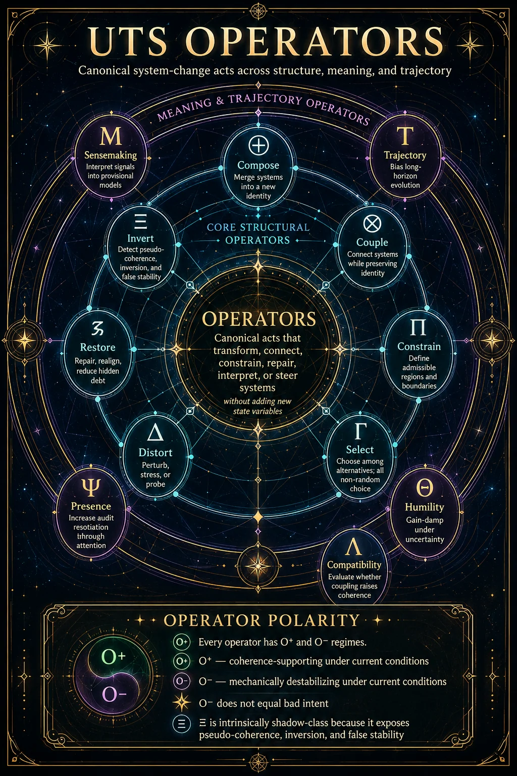
The attached registry divides the 13 operators into two groups: core structural operators and meaning/trajectory operators. The core structural operators include Compose, Couple, Constrain, Select, Distort, Restore, and Invert; the meaning/trajectory operators include Sensemaking, Trajectory, Humility, Compatibility, Sacred Boundary, and Presence.
For this technical module, we do not need to recreate every operator spec sheet. We only need to define their shared mechanics.
1. Operators Are State-Moving Functions
Each operator can be described as:
Operator: Ωᵢ
Input: S(t), U-layer, constraints, forcing, context
Action: state transformation
Output: S(t+1), diagnostic residue, possible regime shift
Example:
ℛ Restore:
Input: H↑, ε↑, R available, Au sufficient
Action: reduce hidden debt, correct error, rebuild alignment
Output: H↓, ε↓, O↑, R temporarily consumed or strengthened
Another example:
Ξ Invert:
Input: apparent coherence, suspicious Φ/O divergence, low Au, rising ι
Action: expose pseudo-coherence or harmonic mismatch
Output: ι clarified, Au demand increases, false stability destabilized
2. Operator Polarity
Every operator can express as O⁺ or O⁻, except Ξ, which is intrinsically shadow-class in the registry. The attachment clarifies that O⁻ does not mean “bad intent”; it means mechanically destabilizing under current conditions.
This is crucial.
An operator’s polarity is not moral. It is structural.
| Operator | O⁺ Expression | O⁻ Expression |
|---|---|---|
| Π Constrain | Protects coherence, boundaries, admissibility | Overconstrains, hides error, suppresses repair |
| Γ Select | Chooses coherence-preserving pathway | Selects proxy success over real coherence |
| Δ Distort | Stress-tests, probes, reveals weakness | Overloads system, produces avoidable fracture |
| ℛ Restore | Repairs hidden debt and reintegrates function | Cosmetic repair, premature closure |
| Μ Sensemaking | Builds provisional interpretive model | Freezes narrative too early |
| Θ Humility | Dampens gain under uncertainty | Becomes avoidance or under-selection |
| Σ Sacred Boundary | Protects non-negotiable invariants | Becomes rigid absolutism if detached from auditability |
| Ψ Presence | Raises audit resolution | Can become passive witnessing without sufficient action if uncoupled from Γ/ℛ |
The key is condition-dependence:
The same operator can preserve coherence in one context and destabilize coherence in another.
V. Localization Layer: U0–U8
The localization layer answers:
Where does the state-change manifest?
U-layers are not variables. They are coordinates. The registry defines them as locations where effects manifest, from substrate through environment, and explicitly states that repair must occur at the same or lower layer than the failure origin.
1. U-Layer Stack
| Layer | Technical Function |
|---|---|
| U0 | Substrate: physical/material limits |
| U1 | Power/budgets: energy, time, compute, money, attention |
| U2 | Configuration: permissions, access, gates, boundaries |
| U3 | Execution: runtime behavior, actuation |
| U4 | Classification: models, metrics, narratives, labels |
| U5 | Coordination: timing, sequencing, protocols |
| U6 | Coherence field: cross-domain alignment/coupling |
| U7 | Memory: recurrence, hysteresis, persistence |
| U8 | Environment: external forcing, shocks, terrain |
2. Same-or-Lower-Layer Repair Rule
The repair rule is one of the most important technical constraints:
Repair must occur at the same or lower U-layer than the failure origin.
Meaning:
| Failure Origin | Insufficient Repair | Proper Repair Direction |
|---|---|---|
| U0 substrate failure | U4 reframing | U0 material repair |
| U1 budget failure | U3 effort increase | U1 budget correction |
| U2 boundary failure | U4 explanation | U2 boundary redesign |
| U4 classification failure | U3 enforcement | U4 metric/model correction |
| U7 memory failure | one-time U3 action | U7 recurrence/memory repair |
| U8 environmental forcing | internal blame narrative | U8 shielding/adaptation + lower-layer reinforcement |
This rule prevents “symbolic repair” from being mistaken for structural repair.
VI. Interaction Mechanics Layer
The interaction layer answers:
How do systems meet, couple, reflect, invite, amplify, relax, attenuate, or force?
The registry defines interface acts as not operators, but parameterized interface moves inside Π / ⊗ / Δ / ℛ contexts.
That distinction should remain locked.
1. Interface Acts
| Act | Name | Canon Mapping | Technical Role |
|---|---|---|---|
| ⊙ | Alignment | Π(self) + Τ(self) | Self-orientation before coupling |
| →? | Invitation | Π + ⊗ | Non-forcing offer to couple |
| ⇈ | Amplification | Δ⁺ probe + Au↑ | Increase signal strength or contrast |
| ⇩ | Relaxation | Π loosen + Θ↑ | Reduce rigidity/gain |
| ↺ | Reflection | Ψ + FI probe | Return signal for audit |
| ⊘ | Attenuation | Π defensive tighten | Reduce harmful throughput |
| ⚕︎ | Restorative Override | Emergency Π + Δ + ℛ | Interrupt active damage to enable repair |
| ✕ | Force | Π hard override | Coercive constraint; always debt-bearing |
2. Interaction Mechanics as Coupling Parameters
Interaction acts modify coupling conditions.
For example:
→? Invitation
does not force ⊗ coupling.
It opens a bounded coupling possibility while preserving BΣ.✕ Force
does not create legitimate coherence.
It can produce short-term compliance, but generates H unless later metabolized through Au, ℛ, and Σ-compatible repair.↺ Reflection
does not “fix” the system by itself.
It increases auditability by returning the signal for inspection.3. Why Interaction Acts Are Not Operators
They do not create new state-transition primitives.
They are composed from existing operators:
| Interface Act | Reducible To |
|---|---|
| Alignment | Π + Τ |
| Invitation | Π + ⊗ |
| Reflection | Ψ + feedback-integrity probe |
| Attenuation | Π |
| Restorative Override | Π + Δ + ℛ |
| Force | Π hard override |
So they belong in the technical architecture, but not the operator registry.
VII. Gate / Constraint Layer
The gate layer answers:
Is this state-change admissible?
Since the gates already have a project section, this technical module only needs the bridge definition.
Gates do not act as raw power. They test whether an action, interpretation, coupling, selection, or repair pathway is admissible.
A gate failure returns:
∅ = null outcomeThis means the action may still physically occur, but it fails canonically as a coherence-valid move.
For example:
| Gate Failure | Technical Meaning |
|---|---|
| FI-Gate failure | Feedback channel cannot be trusted |
| HR-Gate failure | Certainty is too identity-bound or under-audited |
| MS-Gate failure | Rule applies asymmetrically or rank exempts itself |
| Au-Actuation failure | Action exceeds available traceability |
| Principle Constraint Field failure | Action violates locked invariant structure |
In the full system:
Operator + failed gate ≠ valid state transitionIt may still create effects, but those effects usually appear as:
H↑, ι↑, ε↑, Au↓, BΣ↓, K↓VIII. Diagnostic Layer
The diagnostic layer answers:
How does the system respond under stress, forcing, contradiction, delay, and recurrence?
Diagnostics are not operators. They are computed or inferred from the state vector. The registry names bandwidth and damping as always-on forced-response diagnostics, with additional diagnostics such as slack, reaction latency, memory half-life, meta succession rate, constraint complexity, boundary permeability, and attribution pressure.
1. Bandwidth — 𝓑(t)
Bandwidth measures:
How much forcing the system can absorb before phase transition.
The registry gives its directional dependencies:
𝓑(t) increases with {R, Au, BΣ, O}
𝓑(t) decreases with {H, ε, ι}
Technical interpretation:
| Increases Bandwidth | Decreases Bandwidth |
|---|---|
| Restoration capacity | Hidden debt |
| Auditability | Error/noise |
| Boundary integrity | Inversion |
| Coherence | Proxy pressure |
2. Damping — 𝓓(t)
Damping measures:
How quickly oscillations decay after disturbance.
The registry gives its directional dependencies:
𝓓(t) increases with {R, Au}
𝓓(t) decreases with {H, ι, chronic U8 forcing}
Technical interpretation:
A system with high damping can be disturbed without entering recurring instability.
A system with low damping continues to ring after every shock.
3. Additional Diagnostic Fields
| Diagnostic | Technical Function |
|---|---|
| σ(t) Slack | Buffer before forced-response degradation |
| τ_resp(t) Reaction latency | Time between signal and effective response |
| τ_m(t) Memory half-life | Persistence of repair or relapse pattern |
| μ_meta(t) Meta succession rate | Rate of rulebook churn |
| X_c(t) Constraint complexity | Burden created by constraints |
| Perm(t) Boundary permeability | Degree of boundary throughput |
| AP(t) Attribution pressure | Pressure to assign cause/blame/proxy meaning |
4. Diagnostics as Early-Warning Instruments
Diagnostics allow the system to detect failure before collapse becomes visible.
Example:
O appears stable
Φ is rising
Au is falling
H is accumulating
ι is increasing
𝓓(t) is dropping
Interpretation:
The system may be entering pseudo-coherent stability. It looks successful by proxy, but it is losing repairability, traceability, and harmonic fit.
IX. Lenses and Gain Stack
The lens layer answers:
How is the operator effect biased, amplified, obscured, or redirected?
The registry defines lenses as non-operators and lists gain stack categories from mechanical through technological.
1. Gain Stack
| Gain | Function | Failure Risk |
|---|---|---|
| G₀ Mechanical | Physical scale amplification | Material overextension |
| G₁ Energetic | Power throughput | Burn rate, depletion |
| G₂ Informational | Narrative/perception | Misclassification, propaganda, signal distortion |
| G₃ Emotional | Identity/fear/pride charge | Volatility, escalation |
| G₄ Institutional | Rule/enforcement leverage | Legitimacy failure, asymmetric enforcement |
| G₅ Technological | Automation/scale leverage | Rapid propagation, brittle cascade |
The registry notes that many modern failures involve stacked G₂ + G₄ + G₅.
Technical meaning:
Narrative amplification + institutional enforcement + automation
= high-speed pseudo-coherence risk if Au, FI, Θ, and ℛ are insufficient.
2. Structural Lenses
| Lens | Technical Meaning |
|---|---|
| Ω | Observability distribution: who/what can see what |
| P-field | Position/influence geometry |
| RG | Resource gatekeeping |
| SS | Sovereign subfields |
These lenses do not create action, but they alter how action behaves.
For example:
Same operator + different Ω = different auditability outcome.
Same repair attempt + different RG = different restoration throughput.
Same coupling + different P-field = different asymmetry risk.
X. Regime Layer
The regime layer answers:
What recurring composite pattern has the system entered?
Regimes are not operators. The registry defines composite regimes as named patterns, such as LOS, Repair-First Meta, Extraction Regime, Smurfing, CAN, and Crisis Loop.
1. Regime Formation
A regime forms when:
operator sequence + state condition + U-layer localization + gain/lens pattern + diagnostic profilebecomes stable or recurrent.
2. Example: Crisis Loop
Registry composition:
Crisis Loop = 𝓑 breach + 𝓓 low + τ_m shortTechnical interpretation:
A system enters recurring crisis when:
- shocks exceed bandwidth,
- damping is too low to absorb oscillation,
- memory half-life is too short to preserve repair,
- responses become reactive instead of restorative,
- hidden debt accumulates faster than restoration capacity.
3. Example: Extraction Regime
Registry composition:
Extraction Regime = Π + ⊗ without Λ / ΘTechnical interpretation:
Coupling occurs under constraint, but compatibility and humility are missing. The result may produce throughput, compliance, or gain, but it does not produce mutual coherence.
Likely state signature:
Φ↑ short-term
K↓
BΣ↓
H↑
ι↑
O↓ over time
XI. Sanity Constraints
The registry gives several canonical sanity constraints.
These should become the technical law-check layer for the system.
1. Restoration vs Load
R_eff > Load × Gain_stack ⇒ O tends to increaseIf effective restoration capacity exceeds amplified load, coherence tends to recover.
R_eff < Load × Gain_stack ⇒ collapse amplifiesIf load exceeds repair capacity, collapse propagates.
2. Complexity vs Auditability
X_c > Au_eff ⇒ H↑When constraint complexity exceeds effective auditability, hidden debt increases.
This is one of the central system laws for bureaucracy, software, law, AI governance, institutional systems, and spiritual/social frameworks.
3. Shock vs Bandwidth
Shock > 𝓑(t) ⇒ regime shift likelyWhen forcing exceeds bandwidth, the system does not simply “get stressed.” It may transition into another regime.
4. Latency and Legitimacy
Eₓ↑ + τ_resp↑ + asymmetry ⇒ legitimacy shockWhen exposure rises, response latency increases, and asymmetry is visible, legitimacy can collapse quickly.
XII. Minimal Stack-Wide Workflow
The registry gives the minimal method:
- localize symptoms,
- identify moving variables,
- estimate bandwidth and damping,
- enforce gates,
- apply minimal operator sequence,
- validate over time,
- normalize baseline.
For the technical module, we can expand that into a practical workflow.
Step 1 — Localize Symptoms
Ask:
Where is the failure actually occurring?Possible answers:
| Symptom | Likely Layer |
|---|---|
| metric distortion | U4 |
| role confusion | U2 |
| timing failure | U5 |
| recurrence/relapse | U7 |
| resource depletion | U1 |
| environmental shock | U8 |
| runtime malfunction | U3 |
Step 2 — Identify Moving Variables
Ask:
Which parts of S are changing?Example:
Au↓, H↑, Φ↑, O↓This indicates proxy success is rising while real coherence and auditability decline.
Step 3 — Estimate Forced Response
Ask:
Can the system absorb this forcing?
Can it stop oscillating after disturbance?
Use:
𝓑(t) = bandwidth
𝓓(t) = damping
σ(t) = slack
τ_resp(t) = response latency
τ_m(t) = memory half-life
Step 4 — Enforce Gates
Ask:
Is the proposed action admissible?If not:
return ∅or redesign the action.
Step 5 — Apply Minimal Operator Sequence
The correct sequence is usually not “do more.”
It is:
minimum operator sequence needed to restore coherence without unnecessary debt.Example:
Ψ → Μ → Ξ → Π → ℛ → ΤMeaning:
- increase attention/audit resolution,
- interpret signals provisionally,
- detect pseudo-coherence,
- constrain the harmful channel,
- repair hidden debt,
- reorient trajectory.
Step 6 — Validate Over Time
Ask:
Does the repair persist across U5/U7?One-time improvement is not enough. The repair must survive timing, recurrence, and memory.
Step 7 — Normalize Baseline
Ask:
Has the system returned to a better baseline, or merely stabilized the crisis?True repair should produce:
H↓
ε↓
ι↓
Au↑
R↑ or R restored
O↑
BΣ stable
K improved where coupling is present
XIII. Technical Example
Scenario
A system appears successful because its performance metrics are rising, but internal workers, users, or dependent nodes are reporting breakdown, exhaustion, and incoherence.
UTS Translation
Φ↑
O↓
H↑
ε↑
Au↓
R overloaded
BΣ weakening
ι↑
Likely U-Layers
| Layer | Failure |
|---|---|
| U1 | insufficient real budget / time / energy |
| U2 | boundary and role misconfiguration |
| U4 | metric/proxy misclassification |
| U5 | timing and response latency failures |
| U7 | recurring hidden debt accumulation |
Likely Regime
Pseudo-coherent basin
or
Extraction Regime
or
Crisis Loop if 𝓑 has already been breached
Diagnostic Pattern
X_c > Au_eff
R_eff < Load × Gain_stack
τ_resp↑
𝓓(t)↓
τ_m short
Minimal Operator Sequence
Ψ → Μ → Ξ → Π → Λ → ℛ → ΤInterpretation
Presence raises audit resolution. Sensemaking interprets the reports. Inversion detection separates real coherence from proxy success. Constraint blocks the harmful throughput. Compatibility evaluates whether the coupling structure can remain. Restore reduces hidden debt. Trajectory reorients the system away from proxy capture.
XIV. Project Placement
This module should sit above the remaining spec sheets:
UTS — Operator System
  00 — Operator System Technical Architecture
  01 — Canonical State Vector Overview
  02 — State Variable Spec Sheets
  03 — U-Layer Localization System
  04 — Interaction Mechanics
  05 — Lenses and Gain Stack
  06 — Crosswalk Tables
  07 — Applied Audit Workflow
Since gates already have their own section, this module should only cross-reference them rather than duplicate them.
XV. Canon Closure
The technical architecture can be summarized as:
Operators do not operate on stories.
They operate on state.

State does not float freely.
It localizes through U-layers.

Layer localization does not authorize action.
Gates determine admissibility.

Admissible action does not guarantee stability.
Diagnostics reveal forced-response limits.

Repeated diagnostic/operator/layer patterns become regimes.

Regimes do not require new primitives.
They are named compositions of existing mechanics.
Final compressed version:
UTS is a state-transition architecture. Operators move the canonical state vector. U-layers localize the movement. Gates test admissibility. Lenses and gains shape expression. Diagnostics reveal stress behavior. Regimes name recurring compositions. Restoration occurs by identifying the true layer of failure, selecting the minimal admissible operator sequence, and validating repair over time.