0. Purpose
The U-Layer Localization System is the UTS method for identifying where a state change, failure, distortion, repair, coupling event, or regime pattern manifests within a system.
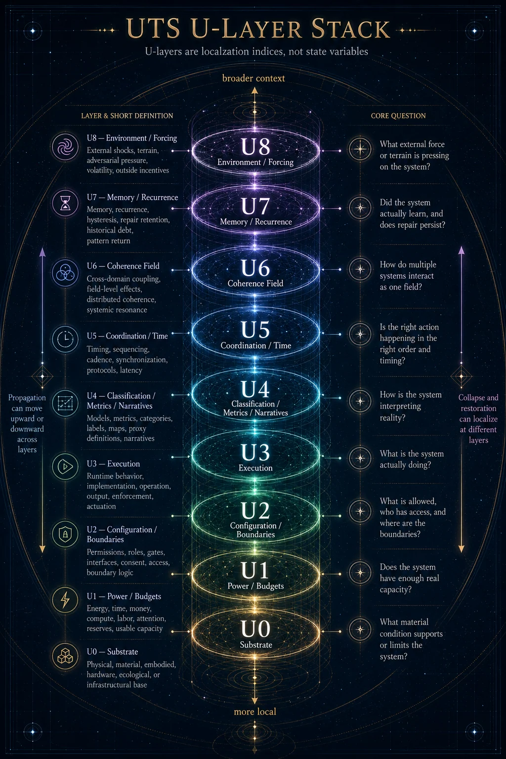
The operator registry defines U-layers as localization indices, not variables. They are coordinates for where effects manifest.
This distinction is crucial.
A U-layer does not act by itself.
U4 does not “cause” distortion.
A classification failure may localize at U4.

U2 does not “create” boundaries.
Boundary integrity failures often manifest at U2.

U7 does not “repair” memory.
Recurrence or memory effects localize at U7.
The U-layer system answers:
Where is this happening in the stack?
The state vector answers:
What is changing?
The operators answer:
What is changing it?
Diagnostics answer:
How is the system responding under stress?
Regimes answer:
What recurring composite pattern has formed?
I. Core Definition
The U-layer system is the localization architecture of UTS.
It maps system activity across nine layers:
| Layer | Name | Basic Meaning |
|---|---|---|
U0 | Substrate | Physical, material, embodied, or base-system limits |
U1 | Power / Budgets | Energy, time, money, compute, labor, attention, resources |
U2 | Configuration / Boundaries | Permissions, roles, gates, interfaces, boundaries |
U3 | Execution | Runtime behavior, operations, action, actuation |
U4 | Classification | Models, metrics, labels, narratives, maps |
U5 | Coordination / Time | Timing, sequencing, protocols, synchronization |
U6 | Coherence Field | Cross-domain coupling, systemic alignment, field effects |
U7 | Memory / Recurrence | History, hysteresis, persistence, learning, recurrence |
U8 | Environment / Forcing | External shocks, terrain, context, adversarial or environmental pressure |
The registry states the layers this way: U0 substrate, U1 power/budgets, U2 configuration/boundaries, U3 execution, U4 classification/metrics/narratives, U5 coordination/time, U6 coherence field, U7 memory/recurrence, and U8 environment/forcing.
II. Why U-Layers Exist
The U-layer system exists because failures are often mislocalized.
A symptom may appear at one layer while its cause originates elsewhere.
Example:
Visible symptom: U3 execution failure
Actual origin: U2 boundary misconfiguration

Visible symptom: U4 narrative conflict
Actual origin: U1 resource depletion

Visible symptom: U5 coordination delay
Actual origin: U7 unresolved recurrence

Visible symptom: U3 performance drop
Actual origin: U8 environmental forcing
Without U-layer localization, repair often targets what is visible rather than what is causal.
This creates wrong-layer repair.
Wrong-layer repair usually produces:
H↑
R_eff↓
τ_m short
ε recurring
ι↑
O fragile
The system appears to respond, but hidden debt remains.
III. U-Layers Are Not State Variables
A U-layer is a coordinate, not a condition.
State variables describe condition:
O, H, ε, ι, Au, µᵢ, BΣ, K, R, ΦU-layers describe localization:
U0, U1, U2, U3, U4, U5, U6, U7, U8So the correct syntax is not:
U4 is high.
U7 is low.
U2 increased.
The correct syntax is:
H↑ localized at U4.
ε recurring through U7.
BΣ failure at U2.
R_eff insufficient at U1.
Φ/O divergence begins at U4 but stores debt at U1 and U7.
This prevents category collapse.
IV. The Same-or-Lower-Layer Repair Rule
The operator registry gives one of the most important repair constraints:
Repair must occur at the same or lower layer than failure origin.
This can be stated technically as:
If failure originates at Uₙ, repair must reach Uₙ or a lower/root layer that can causally alter Uₙ.This does not mean every repair must act only at the lowest possible layer.
It means repair must reach the layer where the causal constraint is stored.
Examples
| Failure Origin | Wrong-Layer Repair | Proper Repair Direction |
|---|---|---|
| U0 substrate limit | U4 reframing | U0 material correction or adaptation |
| U1 resource depletion | U3 effort demand | U1 budget/resource restoration |
| U2 boundary failure | U4 explanation | U2 permission/interface redesign |
| U3 execution bug | U4 blame narrative | U3 process/runtime correction |
| U4 metric distortion | U3 enforcement | U4 metric/model repair |
| U5 timing mismatch | U4 motivational framing | U5 sequencing/protocol redesign |
| U6 cross-domain incoherence | local U3 patch only | U6 coupling-field restoration |
| U7 recurrence failure | one-time U3 action | U7 memory/hysteresis repair |
| U8 external forcing | internal blame | U8 adaptation/shielding plus lower-layer reinforcement |
This rule protects the system from symbolic or procedural repair that does not reach the actual failure architecture.
V. Layer-by-Layer Technical Summary
U0 — Substrate
U0 localizes material, physical, embodied, biological, infrastructural, or base-system constraints.
It answers:
What are the hard substrate conditions?
Examples:
hardware limits
physical infrastructure
body/material condition
biological recovery limits
energy physics
geography
material decay
substrate fragility
Common state expressions:
O constrained by material limits
H stored as deferred maintenance
ε as physical malfunction
R as material repair capacity
Φ distorted by ignoring substrate cost
Core warning:
No amount of narrative, policy, or execution pressure can bypass true substrate limits without creating hidden debt.U1 — Power / Budgets
U1 localizes energy, money, time, compute, labor, attention, capacity, and resource budgets.
It answers:
What fuels the system, and is there enough real capacity?
Examples:
funding
time
energy
attention
compute
staffing
maintenance budget
care capacity
operating margin
Common state expressions:
H as unpaid resource debt
R limited by lack of slack
ε as overload symptoms
Φ↑ through unsustainable extraction
O↓ when load exceeds real capacity
Core warning:
A resource failure cannot be repaired by demanding better execution.If the system lacks budget, time, attention, or energy, U3 performance pressure usually increases hidden debt.
U2 — Configuration / Boundaries
U2 localizes permissions, interfaces, boundaries, access, roles, gates, and structural configuration.
It answers:
Who or what is allowed to do what, through which interface, under what boundary conditions?
Examples:
roles
permissions
consent
access controls
interfaces
contracts
gates
configuration files
institutional authority paths
AI tool-use permissions
Common state expressions:
BΣ failure
Au loss through unclear roles
H from consent ambiguity
K unreliable under boundary blur
ε from interface mismatch
Core warning:
Boundary failures cannot be repaired by better messaging alone.They require configuration, role, interface, or permission redesign.
U3 — Execution
U3 localizes runtime behavior, process, action, implementation, operation, and actuation.
It answers:
What is actually happening in operation?
Examples:
workflow
runtime behavior
task execution
procedural action
model output
institutional enforcement
software process
human behavior
agent actuation
Common state expressions:
ε as observable misfire
R as operational fix capacity
Au as logs/traces
Φ as task completion
O as functional execution coherence
Core warning:
Execution failure may be real, but execution is often where deeper U1, U2, U4, U5, or U7 failures become visible.Do not assume the visible runtime error is the origin.
U4 — Classification / Metrics / Narratives
U4 localizes models, labels, maps, categories, metrics, narratives, interpretations, and success definitions.
It answers:
How is the system interpreting reality?
Examples:
metrics
diagnoses
labels
risk models
benchmarks
narratives
classification systems
policy categories
symbolic frames
meaning maps
Common state expressions:
Φ/O divergence
ι through meaning inversion
H from misclassification
Au distorted by bad categories
µᵢ weakened by symbol-function split
ε misread as noise instead of signal
Core warning:
If the map is wrong, the system may repair the wrong thing beautifully.U4 is one of the most common entry points for pseudo-coherence because classification can make incoherence appear coherent.
U5 — Coordination / Time
U5 localizes timing, sequence, rhythm, synchronization, protocol, scheduling, latency, and temporal order.
It answers:
Is the right thing happening in the right order, at the right time, with the right pacing?
Examples:
sequencing
protocol timing
response latency
synchronization
handoffs
feedback timing
repair timing
developmental timing
coordination cycles
Common state expressions:
τ_resp increase
K failure through timing mismatch
R delayed
ε from mis-sequencing
H from late repair
O↓ through desynchronization
Core warning:
Correct action at the wrong time can become incoherent.U5 explains why systems with correct components may still fail.
U6 — Coherence Field
U6 localizes cross-domain coupling, field-level alignment, systemic resonance, multi-layer coherence, and whole-system pattern effects.
It answers:
How do multiple domains interact as one coherence field?
Examples:
institution-culture coupling
technology-governance coupling
biology-environment coupling
AI-human workflow coupling
symbolic-material interaction
cross-system resonance
field-wide coherence/incoherence
Common state expressions:
O across domains
K across multiple systems
H exported between domains
ι field-level pseudo-coherence
R requiring multi-domain repair
BΣ between interacting systems
Core warning:
A local repair can fail if the broader coherence field keeps regenerating the same failure.U6 is where multi-domain interactions become visible.
U7 — Memory / Recurrence
U7 localizes memory, recurrence, hysteresis, history, habit, repair persistence, institutional learning, and relapse patterns.
It answers:
Does the system remember, repeat, retain, or relapse?
Examples:
historical patterns
recurring failures
institutional memory
technical debt recurrence
repair persistence
habit loops
hysteresis
training effects
legacy constraints
Common state expressions:
τ_m short
H returning
ε recurring
µᵢ weakened through amnesia
R failing to persist
O unvalidated over time
Core warning:
A repair that does not survive recurrence is not fully integrated.U7 is the truth test of restoration.
U8 — Environment / Forcing
U8 localizes external pressure, shocks, terrain, adversarial conditions, environmental volatility, ecosystem constraints, and context outside the system.
It answers:
What is pressing on the system from outside?
Examples:
market shocks
weather/ecology
adversarial attacks
social pressure
regulatory change
technological shift
supply disruption
external incentives
terrain mismatch
Common state expressions:
ε from external shock
𝓑 breach
𝓓 lowered by chronic forcing
R consumed by adaptation
H from ignored terrain
Φ distorted by context blindness
Core warning:
Do not misclassify environmental forcing as internal failure.U8 localization prevents systems from blaming internal parts for external pressure they were never designed to absorb.
VI. State Variables Across U-Layers
Every state variable can localize differently across the stack.
Example: Hidden Debt Across Layers
| Layer | H Expression |
|---|---|
| U0 | deferred material maintenance |
| U1 | resource depletion |
| U2 | boundary/permission debt |
| U3 | operational workaround debt |
| U4 | metric/model debt |
| U5 | timing/protocol debt |
| U6 | cross-domain incoherence debt |
| U7 | recurrence/history debt |
| U8 | unmanaged environmental exposure debt |
Example: Auditability Across Layers
| Layer | Au Expression |
|---|---|
| U0 | substrate inspection |
| U1 | resource-flow traceability |
| U2 | permission/interface audit |
| U3 | execution logs/process visibility |
| U4 | model/metric/narrative audit |
| U5 | protocol/timing traceability |
| U6 | cross-domain effect visibility |
| U7 | recurrence/memory inspection |
| U8 | external/internal cause distinction |
Example: Fitness Proxy Across Layers
| Layer | Φ Expression |
|---|---|
| U1 | profit, productivity, budget efficiency |
| U3 | output, completion, runtime performance |
| U4 | benchmark, score, category success |
| U5 | schedule adherence |
| U7 | retention/recurrence metric |
| U8 | adaptation or survival signal |
The layer tells us where the proxy is measuring and, equally important, what it may be ignoring.
VII. Operators Across U-Layers
Operators can act at different layers.
The same operator changes meaning depending on localization.
Example: Π Constrain
| Layer | Π Expression |
|---|---|
| U0 | physical containment |
| U1 | budget/resource limit |
| U2 | permission boundary |
| U3 | runtime guardrail |
| U4 | classification rule |
| U5 | timing/protocol constraint |
| U6 | cross-domain invariant boundary |
| U7 | memory/recurrence constraint |
| U8 | environmental shield |
Example: ℛ Restore
| Layer | ℛ Expression |
|---|---|
| U0 | material repair |
| U1 | resource replenishment |
| U2 | boundary restoration |
| U3 | process correction |
| U4 | model/metric repair |
| U5 | sequencing repair |
| U6 | field/coupling restoration |
| U7 | recurrence repair |
| U8 | adaptation to external forcing |
Example: Ξ Invert
| Layer | Ξ Expression |
|---|---|
| U1 | growth masking depletion |
| U2 | boundary erosion framed as unity |
| U3 | compliance mistaken for function |
| U4 | metric mistaken for truth |
| U5 | delay framed as strategy |
| U6 | field fragmentation framed as alignment |
| U7 | recurrence framed as isolated event |
| U8 | external forcing misread as internal defect |
The operator remains the same.
The layer changes what it acts upon.
VIII. Diagnostics Across U-Layers
Diagnostics are often layer-sensitive.
The registry defines bandwidth and damping as forced-response diagnostics computed from state variables rather than operators.
1. Bandwidth — 𝓑(t)
Bandwidth asks:
How much forcing can the system absorb before phase transition?
Layer implications:
U0 bandwidth = material tolerance
U1 bandwidth = resource reserve
U2 bandwidth = boundary/interface tolerance
U3 bandwidth = runtime operating margin
U4 bandwidth = interpretive flexibility
U5 bandwidth = timing/coordination tolerance
U6 bandwidth = cross-domain coherence tolerance
U7 bandwidth = recurrence/memory tolerance
U8 bandwidth = environmental shock tolerance
2. Damping — 𝓓(t)
Damping asks:
How quickly does disturbance decay?
Layer implications:
U3 damping = operational stabilization
U4 damping = narrative/model correction
U5 damping = timing resynchronization
U7 damping = recurrence reduction
U8 damping = adaptation to chronic forcing
A system can damp operationally while failing at memory.
Example:
U3 stabilizes after each incident
but U7 recurrence remains unchanged
This means the system fixes events but not patterns.
IX. U-Layer Mislocalization Patterns
1. U3 Blame for U1 Failure
The system treats resource depletion as poor execution.
U1 origin: insufficient time, staff, energy, budget
U3 misrepair: demand better performance
Result: H↑, R↓, ε recurring
2. U4 Explanation for U2 Boundary Failure
The system explains boundary collapse instead of redesigning the boundary.
U2 origin: unclear permission/interface/role
U4 misrepair: narrative clarification only
Result: BΣ remains weak, H↑
3. U3 Patch for U4 Metric Failure
The system enforces behavior around a bad metric.
U4 origin: wrong proxy
U3 misrepair: stricter compliance
Result: Φ↑, O↓, ι↑
4. U4 Framing for U7 Recurrence
The system narrates recurring patterns as isolated events.
U7 origin: memory/recurrence failure
U4 misrepair: “this was unusual”
Result: τ_m short, ε returns
5. Internal Blame for U8 Forcing
The system treats environmental pressure as internal defect.
U8 origin: external shock/terrain/context
U3/U4 misrepair: blame local actors or local process
Result: AP↑, H↑, wrong repair
6. U2 Overconstraint for U4 Ambiguity
The system adds boundaries or rules because classification is unclear.
U4 origin: bad model/category
U2 misrepair: more permissions/rules
Result: X_c↑, Au_eff↓, H↑
This directly connects to the registry constraint:
X_c > Au_eff ⇒ H↑X. Layer Cascades
Failures often propagate across layers.
1. Downward Cascade
A high-layer misclassification produces lower-layer cost.
U4 bad metric
→ U3 distorted execution
→ U1 resource depletion
→ U7 recurring debt
Example:
wrong success metric
→ people optimize the wrong behavior
→ repair capacity is consumed
→ the pattern repeats
2. Upward Cascade
A lower-layer constraint produces higher-layer narrative distortion.
U1 resource depletion
→ U3 performance errors
→ U4 blame narrative
→ U7 recurrence
Example:
not enough capacity
→ visible failures
→ story becomes “people are not trying hard enough”
→ same failure returns
3. Cross-Domain Cascade
A failure in one domain propagates through U6 into another.
AI system metric distortion
→ institutional workflow distortion
→ human repair burden
→ legitimacy crisis
This is a U6-mediated pattern because multiple domains co-produce the failure.
XI. U-Layers and Regimes
Regimes are recurring compositions of operators, state variables, diagnostics, and layers.
The registry defines regimes as named patterns, not operators.
Example: Crisis Loop
Registry composition:
Crisis Loop = 𝓑 breach + 𝓓 low + τ_m shortLayer view:
U8 shock or U1 overload breaches bandwidth
U3 crisis response stabilizes temporarily
U7 memory fails to retain repair
U5 response latency grows
Crisis recurs
Example: Extraction Regime
Registry composition:
Π + ⊗ without Λ / ΘLayer view:
U2 boundary weakened
U1 resource burden transferred
U3 execution continues
U4 proxy declares success
U7 hidden debt accumulates
U6 coupling field degrades
Example: Pseudo-Coherent Basin
Layer view:
U4 classification stabilizes false map
U3 behavior conforms to map
U1 hidden cost accumulates
U2 boundaries weaken
U7 recurrence normalizes pattern
U6 field appears stable but exports incoherence
Example: Repair-First Meta
Registry composition:
ℛ + Π + Σ dominanceLayer view:
U2 boundaries protected
U4 proxy subordinated to coherence
U1 repair budget preserved
U5 repair timing prioritized
U7 repair memory retained
XII. U-Layer Audit Workflow
A practical U-layer audit should proceed in order.
Step 1 — Identify the Visible Symptom
Ask:
Where does the problem appear?Examples:
U3 execution error
U4 narrative conflict
U5 coordination delay
U7 recurrence
Step 2 — Separate Manifestation Layer From Origin Layer
Ask:
Is this where the problem appears, or where it originates?This prevents symptom repair.
Step 3 — Map State Variables by Layer
Ask:
Which variables are moving, and at what layers?Example:
ε↑ at U3
H↑ at U1
Φ↑ at U4
R↓ at U7
This means execution errors are visible, but hidden resource debt and recurrence failure are deeper causes.
Step 4 — Identify Operator Activity
Ask:
Which operators are active, distorted, missing, or needed?Example:
Γ selecting for Φ
Π suppressing ε
Ξ absent
ℛ mislocalized
Step 5 — Check Diagnostics
Ask:
Has bandwidth been breached?
Is damping low?
Is recurrence short?
Is attribution pressure rising?
Step 6 — Apply Same-or-Lower-Layer Repair Rule
Ask:
What layer must repair reach for H to decrease?Step 7 — Validate Through U7
Ask:
Does the repair persist through recurrence?If not, repair did not fully integrate.
XIII. Minimal Layer-Localization Template
This can become the standard audit card.
# U-Layer Localization Audit

## 1. Visible Symptom
- What is observed?
- At what U-layer does it appear?

## 2. Candidate Origin Layer
- Where might the failure originate?
- What evidence supports this?

## 3. State Vector Movement
- O:
- H:
- ε:
- ι:
- Au:
- µᵢ:
- BΣ:
- K:
- R:
- Φ:

## 4. Operator Pattern
- Active operators:
- Missing operators:
- Distorted operators:

## 5. Diagnostic Pattern
- 𝓑(t):
- 𝓓(t):
- σ(t):
- τ_resp(t):
- τ_m(t):
- X_c(t):
- AP(t):

## 6. Repair Requirement
- What layer must repair reach?
- What same-or-lower-layer action is required?

## 7. Recurrence Test
- How will repair be validated at U7?
XIV. Common Layer Statements
These are useful project-ready formulations.
The failure appears at U3 but originates at U1.The metric is U4-localized, but the debt is stored at U1 and U7.The system is attempting U4 repair for a U2 boundary failure.The coupling problem is U6-visible but U2/U5-originating.The repair is U3-effective but U7-incomplete.The proxy measures U3 output while ignoring U1 depletion and U7 recurrence.The environmental forcing is U8, but the system is misclassifying it as U3 failure.XV. Relationship to the State Vector
The U-layer system gives every state variable a location.
A complete UTS state statement should ideally include both variable and layer.
Weak statement:
Hidden debt is rising.Stronger statement:
H↑ at U1 and U7, caused by U4 proxy distortion and U5 repair delay.Weak statement:
Compatibility is low.Stronger statement:
K↓ due to U5 timing mismatch and U2 boundary ambiguity, despite U4 agreement.Weak statement:
The system has poor auditability.Stronger statement:
Au is high at U3 through logging, but low at U4 metric design and U7 recurrence tracking.This is the practical power of U-layer localization.
XVI. Canon Notes
- U-layers are localization indices, not variables.
- U-layers describe where effects manifest.
- State variables describe what is changing.
- Operators describe what changes state.
- Diagnostics describe forced-response behavior.
- Regimes describe recurring compositions.
- Symptoms can appear at a different layer than their origin.
- Repair must reach the same or lower layer than failure origin.
- Wrong-layer repair increases hidden debt.
- U4 misclassification is one of the most common sources of pseudo-coherence.
- U7 recurrence is the truth test for repair.
- U8 forcing must not be misclassified as internal failure.
- U2 boundary failure often masquerades as U3 behavior failure.
- U1 resource failure often masquerades as U3 effort failure.
- U-layer localization prevents repair theater.
XVII. Compressed Definition
U-Layers = localization coordinates that identify where state movement, operator effects, failures, repairs, diagnostics, and regimes manifest within the UTS stack.Short form:
U-layers tell us where the system is changing.
Final operational rule:
Do not repair the layer where the symptom appears until you have checked the layer where the failure originates.