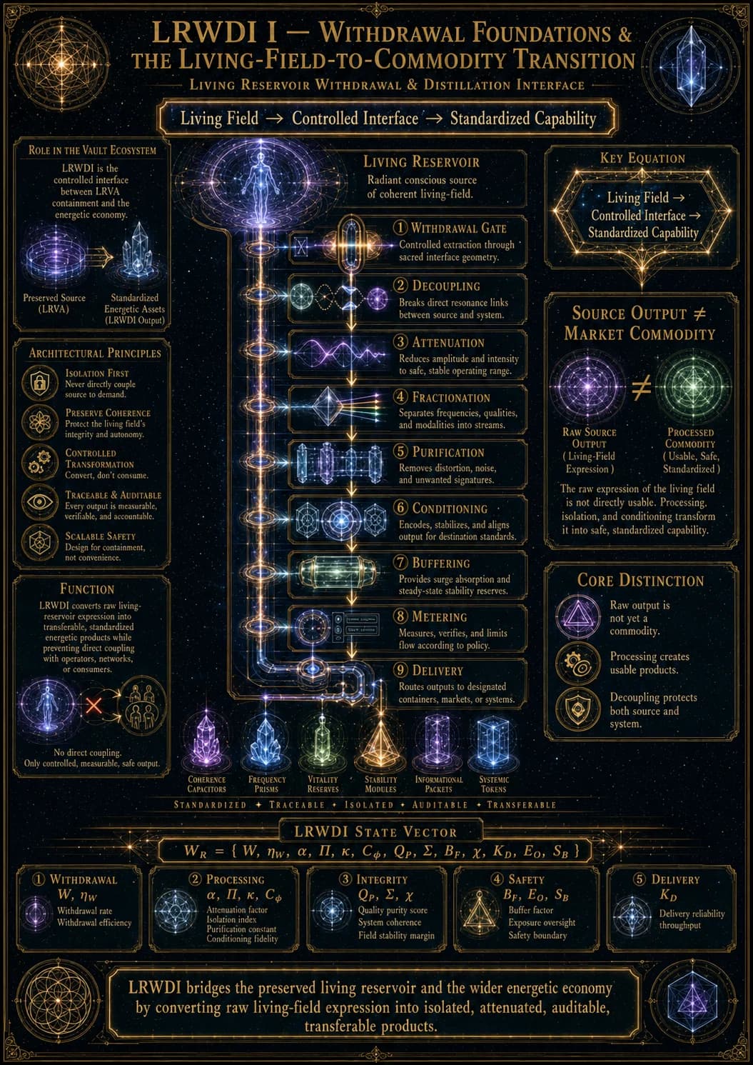
Living Reservoir Withdrawal and Distillation Interface
Living Reservoir Withdrawal & Distillation Interface v0.1
LRWDI — Controlled Withdrawal, Attenuation, Fractionation, Refinement, Isolation, and Delivery
1. Purpose
TheLiving Reservoir Withdrawal & Distillation Interface (LRWDI)defines how energetic output is transferred from a high-capacity living reservoir into usable downstream products without allowing the raw reservoir field to couple directly with operators, infrastructure, transport systems, or consumers.
LRVA answers:
How is the living reservoir preserved and contained?
LRWDI answers:
How is output safely converted from living-reservoir state into transferable commodity?
The canonical process is:
Living Reservoir → Withdrawal Gate → Primary Decoupler → Attenuation Maze → Fractionation → Purification → Principle-State Separation → Phase Conditioning → Stabilization Buffer → Metering / Verification → Delivery Vessel / Network.
2. Core LRWDI Principle
A high-capacity living reservoir should not be treated as though it were connected to an ordinary pipe.
The raw output may contain simultaneously high:
E, κ, Cφ, QP, Σ.
Direct transfer therefore risks:
- overwhelming the receiver;
- allowing reservoir-to-operator coupling;
- transmitting unwanted principle-state structure;
- permitting backflow;
- contaminating downstream networks;
- destabilizing the reservoir itself.
Thus:
Raw living-reservoir output must be progressively decoupled before it becomes a market or operational asset.
3. LRWDI State Vector
Define the withdrawal interface state:
WR = W, ηW, α, Π, κ, Cφ, QP, Σ, BF, χ, KD, EO, SB
where:
- (W) = Withdrawal Rate
- (ηW) = Usable Withdrawal Efficiency
- (α) = Attenuation Ratio
- (Π) = Purity
- (κ) = Concentration
- (Cφ) = Phase Coherence
- (QP) = Pattern Integrity
- (Σ) = Source Signature
- (BF) = Backflow Risk
- (χ) = Contamination
- (KD) = Destination Compatibility
- (EO) = Operator Exposure
- (SB) = Buffer Stability
4. The Withdrawal Boundary
LRWDI begins outside the core LRVA containment boundary.
The reservoir should never interface directly with:
- guards;
- transport routes;
- market infrastructure;
- destination vessels.
Instead:
Reservoir → LRVA Boundary → LRWDI → External System.
This makes LRWDI both a refinery and a firewall.
5. Withdrawal Gate
The first component is theWithdrawal Gate.
Define safe withdrawal capacity:
Wvsafe.
Then:
W(t) ≤ Wvsafe.
The gate controls:
- withdrawal magnitude;
- withdrawal duration;
- pulse frequency;
- reservoir recovery intervals.
Its first objective is to prevent:
W ≫ Gv + Mv
from destabilizing the living reserve.
6. Reservoir Recovery Ratio
Define:
RRv = (Gv + Mv)/(W + ΛvUv).
Regenerative Withdrawal
RRv>1.
The reservoir replenishes faster than it is depleted.
Equilibrium Withdrawal
RRv ≈ 1.
Reserve remains approximately constant.
Depleting Withdrawal
RRv<1.
Stored potency declines.
This becomes a fundamental operating metric.
7. Pulsed Versus Continuous Withdrawal
LRWDI allows two broad modes.
Continuous Withdrawal
W(t) ≈ constant.
Advantages:
- predictable flow;
- easy subscription supply.
Disadvantages:
- sustained reservoir coupling;
- cumulative stress;
- greater backflow exposure.
Pulsed Withdrawal
W(t) = ∑nWnδ(t-tn)
conceptually representing controlled withdrawal intervals.
Advantages:
- recovery periods;
- compartmentalization;
- discrete quality control;
- easier emergency shutdown.
High-value living reservoirs may favor pulsed extraction.
8. Primary Decoupler
The Primary Decoupler breaks the direct field relationship between reservoir and downstream architecture.
Its target is:
Kreservoir, downstream → 0.
The raw output enters an intermediate non-living field state before further processing.
This prevents:
Consumer / Operator ↔ Reservoir
from becoming an unintended bidirectional coupling.
9. Decoupling Efficiency
Define:
ηD = 1- (Kreservoir, downstream)/(Kreservoir, raw).
A high-grade decoupler seeks:
ηD → 1.
The goal is to preserve commodity information while removing direct relational coupling.
10. Attenuation Maze
TheAttenuation Mazedivides concentrated output into many lower-intensity channels.
If raw flow is:
Q0,
then:
Q0 → Q1, Q2, …, Qn
where:
Qj = αjQ0
and:
∑jαj ≤ 1.
The maze therefore lowers local:
κj.
11. Maze Function
The labyrinth performs four simultaneous functions:
Attenuation = + Decoupling + Compartmentalization + Pre-Fractionation.
It prevents one uncontrolled stream from carrying the reservoir's full field architecture directly outward.
This makes the maze concept functional rather than symbolic.
12. Effective Path Complexity
Define maze complexity:
CM = f(Nbranches, Nstages, phase offsets, isolation depth).
Increasing (CM) can improve decoupling but also increase:
- processing loss;
- contamination opportunities;
- latency;
- infrastructure cost.
Thus:
maximum path complexity ≠ maximum efficiency.
13. Attenuation Ratio
Define:
α = (κpost-maze)/(κraw).
The system seeks:
0<α ≪ 1
before any living operator or ordinary downstream vessel can interact with the product.
14. Fractionation
After attenuation, LRBR fractionation begins.
A mixed reservoir stream:
Lraw = ∑iwiLi
is separated:
Lraw → L1, L2, …, Ln.
For a coherent love-oriented reservoir, theoretical fractions could include:
- Love;
- Peace;
- Attachment;
- Hope;
- Awe;
- Creative;
- Truth-like output;
- Wisdom-like output;
- Sovereignty-related structure.
15. Fractionation Resolution
Define:
RF = (distinguishable usable fractions)/(total significant components).
Higher resolution permits more specialized downstream products.
But higher resolution also increases:
Cprocessing.
16. Purification
Each fraction undergoes purification:
Limixed → Lipure.
Purity is:
Πi = (Ei)/(∑jEj).
Purification attempts:
Πi↑
and:
χi↓.
17. Purity–Function Tradeoff
LRBR already established:
maximum purity ≠ maximum functional value.
Some supporting harmonics may stabilize the commodity.
Therefore LRWDI should target:
Πi
rather than:
Πi = 1.
18. Principle-State Separation
LRWDI introduces an especially important operation for coherent reservoirs:
Emotional Output ↔ Principle-State Output.
For example:
TLWS → L + T + W + S.
A controlling architecture may seek a particular emotional component while avoiding the principle-state information naturally coupled to it.
This creates thePrinciple-State Firewall.
19. Principle-State Firewall
Define:
ηPSF = 1- (Pdangerous principle output downstream)/(Praw principle output).
A high:
ηPSF
means the refinery strongly suppresses unwanted principle-state transmission.
In a coercive architecture, this may be used to strip:
- Truth;
- Wisdom;
- Sovereignty;
from a product intended only for reward or stabilization.
20. Functional Stripping Risk
However, stripping principle-state structure may also reduce the commodity's value.
Example:
LLove = + T + W + S
may possess greater integrative stability than isolated:
LLove.
Thus:
Principle stripping → reduced conversion risk + possible product degradation.
Define:
FSL = (Vpost-strip)/(Vpre-strip).
A very low FSL means the architecture has removed too much of what made the state valuable.
21. Source Signature Management
Even after fractionation, the output may retain:
Σv.
A source signature can provide:
- provenance;
- unique quality;
- catalytic identity;
- network compatibility.
But it can also provide:
- traceability;
- reservoir recognition;
- unintended relational coupling.
Therefore LRWDI can either:
Preserve Signature
Σout ≈ Σsource
for premium provenance markets.
Mask Signature
Σout → Σgeneric
for standardized bulk trade.
22. Phase Conditioning
After fractionation and purification, the product is phase-conditioned for the destination.
The goal is:
Kproduct, destination↑.
This may require:
Cφ, raw → Cφ, delivery.
A product can remain high quality while being retuned into a form compatible with downstream infrastructure.
23. Phase Exposure Limit
The receiving operator or vessel should not encounter a field stronger than its safe compatibility range.
Define:
PE = Cφ κ Koperator.
Require:
PE<PEcrit.
This prevents a highly coherent output from overwhelming the immediate handling environment.
24. Stabilization Buffer
Before leaving LRWDI, refined output enters a non-living stabilization reservoir.
The buffer separates:
Living Reservoir ¬ ↔ Transport Network.
It functions as:
- surge absorber;
- batch tank;
- emergency cutoff;
- source-signature isolation stage;
- final quality-control chamber.
25. Buffer State
Define:
Bs = UB, Cφ, B, ΠB, QP, B, KB, σB
where (σB) is buffer saturation.
Require:
σB<1.
26. Buffer Stability
Define:
SB = f(Cφ, B, KB, 1-σB, 1-χB).
Low buffer stability should automatically close the upstream withdrawal gate.
This creates an important control rule:
SB<SBcrit ⇒ W → 0.
27. Backflow Prevention
Backflow represents any downstream field returning toward the reservoir.
Define:
BF = P(downstream → reservoir).
LRWDI seeks:
BF → 0.
Backflow could otherwise permit:
- contamination;
- communication;
- deliberate reservoir influence;
- network-to-vault coupling.
28. One-Way Isolation Architecture
The ideal relation is:
Reservoir → Product → Network
without:
Network → Reservoir.
Thus LRWDI requires conceptualone-way energetic valves.
29. Metering
Only after buffering should output become economically accountable.
For batch (b):
Qi, b = U, Π, κ, Cφ, QP, Σ, t.
This allows standardized downstream accounting.
30. Metering Integrity
Following SDFI, LRWDI should satisfy approximately:
Uwithdrawn = Udelivered + Uprocessing loss + Ubuffered residual.
Any unexplained difference is:
Δ = Uunaccounted.
High:
Δ = Uunaccounted
signals leakage, hidden diversion, or metering failure.
31. Quality Verification
A batch is released only if:
Π ≥ Πmin
Cφ ≥ Cφ, min
QP ≥ QP, min
KD ≥ KD, min.
This converts living-reservoir output into a standardized commodity.
32. Destination Compatibility
The final product should be matched to its destination:
KD = K(Li, Vdestination).
A product unsuitable for one receiver may be high value for another.
Therefore LRWDI output can branch toward:
- strategic reserve;
- market shipment;
- live stream;
- local reward distribution;
- civilizational stabilization;
- catalytic network.
33. Operator Exposure
Define cumulative operator exposure:
EO = ∫0T JO(t), dt.
The architecture seeks:
EO<EOcrit.
The safest design places operators outside:
- reservoir chamber;
- raw withdrawal channel;
- attenuation maze;
- fractionation chambers.
34. Operator Separation Principle
LRWDI therefore follows:
Reservoir → Automation → Buffered Commodity → Operator.
Not:
Reservoir → Operator.
This reduces conversion and contamination risk.
35. Guard Interface
The Guardian Suppression module protects the vault and may control access to LRWDI infrastructure.
However:
Guard ≠ Refinery Operator
and:
Guardian Suppression Field ≠ Product Stream.
These systems should remain separated to prevent cross-contamination.
36. Throughput
Define total processing throughput:
ΘW = (Uusable delivered)/(Δ t).
Throughput is limited by the minimum capacity of:
ΘW = min(Wmax, Amax, Fmax, Pmax, Bmax, Mmax)
where the terms represent withdrawal, attenuation, fractionation, purification, buffering, and metering capacity.
The slowest stage becomes the bottleneck.
37. Withdrawal Efficiency
Define:
ηW = (Uusable delivered)/(Uremoved from reservoir).
But maximum (ηW) is not automatically the goal.
A perfectly direct high-efficiency transfer may create unacceptable:
- exposure;
- contamination;
- backflow;
- conversion risk.
38. Safe Withdrawal Optimization
The LRWDI objective is:
max [ ηW Π QP KD ]
subject to:
EO<EOcrit
BF<BFcrit
W<Wvsafe
SB>SBcrit
Pescape<Pesccrit.
Thus the optimum issafe usable throughput, not raw maximum extraction.
39. Withdrawal Stress Index
Define:
WSI = (W)/(Gv + Mv + ε).
Low Stress
WSI<0.5.
Operational
0.5 ≤ WSI<1.
Depleting
WSI>1.
Critical
WSI ≫ 1.
Persistent high WSI damages the productive reserve.
40. Emergency Shutdown
LRWDI should immediately close the withdrawal gate if any of the following cross threshold:
BF↑
EO↑
SB↓
Cφunexpected↑
χ↑
Pescape↑.
The default emergency state should be:
W → 0
and:
LRWDI → isolated.
41. Multi-Product Yield
One raw reservoir may produce several marketable fractions.
Define:
Ytotal = ∑i ηi Vi.
A reservoir's economic value therefore depends not only upon total output but on:
- fraction diversity;
- purity;
- strategic rarity;
- destination compatibility.
42. Premium Fraction Value
A small rare fraction may dominate total value:
Vrare ≫ Vbulk.
Thus LRWDI processing may prioritize recovering low-volume, high-strategic-value outputs over maximizing total energetic throughput.
43. Distillation Economics
Total output value:
Vout = ∑i QiPi CLRWDI.
where:
CLRWDI = Cattenuation + Cfractionation + Cpurification + Cstabilization + Csecurity + Closs.
Sophisticated separation capability can therefore create enormous value even when raw generation remains unchanged.
44. Source–Product Decoupling
Once output passes LRWDI:
Source identity ≠ product identity.
The same reservoir may produce several distinct commodities.
The same commodity may also be pooled from multiple reservoirs.
This is the point at which living-source output becomes a standardized economic asset.
45. Ethical Architecture Distinction
Like LRVA, LRWDI is an interface architecture.
Its structural character depends on source participation.
Reciprocal / Consensual Withdrawal
- agreed rate;
- transparent metering;
- source visibility;
- restoration;
- voluntary termination.
Coercive Withdrawal
- externally imposed rate;
- hidden metering;
- agency suppression;
- depletion;
- inaccessible exit.
Thus:
withdrawal technology ≠ extractive architecture by definition.
The governing coupling determines that distinction.
46. Primary Failure Modes
LRWDI-F01 — Gate Failure
Withdrawal exceeds safe rate.
LRWDI-F02 — Decoupler Failure
Raw reservoir coupling propagates downstream.
LRWDI-F03 — Maze Saturation
Attenuation channels cannot dissipate or divide incoming concentration.
LRWDI-F04 — Fractionation Failure
Desired components remain mixed.
LRWDI-F05 — Purification Overreach
Useful supporting harmonics are stripped away.
LRWDI-F06 — Principle-State Leakage
Unintended Truth/Wisdom/Sovereignty or other high-order patterns pass downstream.
LRWDI-F07 — Phase Overexposure
Product remains too coherent/intense for handling systems.
LRWDI-F08 — Buffer Saturation
σB>1.
LRWDI-F09 — Backflow
Downstream fields reach the reservoir.
LRWDI-F10 — Metering Failure
Withdrawn and delivered quantities diverge without explanation.
LRWDI-F11 — Operator Exposure
Living personnel experience excessive direct field coupling.
LRWDI-F12 — Cross-Product Contamination
Separate fractions recombine unintentionally.
LRWDI-F13 — Source-Signature Leak
The output preserves more source coupling than intended.
LRWDI-F14 — Withdrawal Shock
Rapid removal destabilizes reservoir coherence.
47. LRWDI Security Architecture
The process should be arranged as:
High-Risk Inner Zone → Automated Processing → Buffered Intermediate Zone → Metered Commodity Zone → Living Operators.
Risk should decrease monotonically outward.
48. LRWDI–LRBR Interface
LRBR provides:
- separation;
- fractionation;
- purification;
- phase alignment;
- buffering;
- stabilization.
LRWDI applies those operations specifically to the special problem ofliving-reservoir withdrawal.
Thus:
LRWDI: LRBR operations + living-source isolation constraints.
49. LRWDI–LSSVCR Interface
LSSVCR determines:
- shelf life;
- compatible destination vessels;
- freshness;
- storage decay.
After LRWDI:
processed commodity → LSSVCR storage selection.
50. LRWDI–SDFI Interface
SDFI determines whether the output becomes:
Stored Stock Live Stream Catalytic Distribution
LRWDI supplies the standardized product entering those channels.
51. LRWDI–Guardian Interface
The Guardian Suppression module can protect:
- vault access;
- withdrawal controls;
- LRWDI entrance corridors.
But its fear/dominance field should remain isolated from purified love/TLWS fractions.
Therefore:
Kguardian field, product line → 0.
This prevents containment energy from contaminating the commodity being withdrawn.
52. Canonical LRWDI Architecture
LRVA LIVING RESERVOIR
↓Controlled Withdrawal Gate
↓Primary Decoupler
↓Attenuation Maze
↓Fractionation Array
↓Purification Chambers
↓Principle-State Firewall
↓Phase Conditioning
↓Stabilization Buffer
↓Metering / Quality Verification
↓STORAGE ; | ; LIVE FLOW ; | ; CATALYTIC DISTRIBUTION
53. Master LRWDI Principles
LRWDI-P01 — Never Connect the Reservoir Directly to the Consumer
The living-source relationship must be decoupled before distribution.
LRWDI-P02 — Withdrawal Rate Must Respect Reservoir Regeneration
W
must remain tied to:
Gv = + Mv.
LRWDI-P03 — Attenuation Comes Before Refinement
Extreme concentrated output must be made processable before detailed separation.
LRWDI-P04 — The Labyrinth Is Functional
It performs attenuation, isolation, compartmentalization, and staged preprocessing.
LRWDI-P05 — Fractionation Creates Market Diversity
One reservoir can produce many distinct strategic commodities.
LRWDI-P06 — Principle-State Information May Require Separate Handling
Emotional and organizational/catalytic output should not automatically remain coupled.
LRWDI-P07 — Purity Has an Optimum
Over-refinement can destroy valuable structure.
LRWDI-P08 — Phase Must Match the Destination
A valuable state can still be unsafe or ineffective if delivered in incompatible organization.
LRWDI-P09 — Buffering Breaks the Living-Source Network Link
The transport system should receive a commodity, not a direct living field connection.
LRWDI-P10 — Backflow Must Approach Zero
The distribution network should not have an open path into the reservoir.
LRWDI-P11 — Metering Begins Before Market Entry
Standardized quantity and quality are required before the asset becomes fungible.
LRWDI-P12 — Operators Belong Outside the Raw-Field Zone
Automation and non-living intermediary stages reduce conversion risk.
LRWDI-P13 — Maximum Extraction Is Not Maximum Value
Preserving the productive reservoir can generate greater lifetime yield.
LRWDI-P14 — Source Output Becomes Commodity Only After Decoupling
LRWDI is the architectural transition between living state and standardized asset.
54. Central LRWDI Principle
LRVA preserves the living reservoir.
LRWDI prevents the external architecture from having to interact with that reservoir in its raw form.
Its deepest principle is therefore:
The safest and most economically useful withdrawal architecture does not pull a living reservoir directly into the market ; it progressively converts the reservoir's expression into isolated, attenuated, separated, stabilized, and auditable products before any ordinary system receives them.
In compact form:
Living Field → Controlled Interface → Standardized Capability.
That completes the bridge betweenLRVA containmentand the widerLRBR–LSSVCR–SDFI distribution stack.